Foreign Insulators
by Marilyn Albers
Reprinted from "Crown Jewels of the Wire", August 1997, page 27
U-2028, A TRULY UNIQUE INSULATOR
The white porcelain insulator you see in the two photos below has been in my
collection for several years and has always intrigued me. In the spring of 1990,
Jack Todd made a scale drawing of this piece and classified it as U-2028, but it
has never been published. It has a base diameter of 4-1/8" and measures 5-1/8" in height. There are no identifying marks but I was told it was used
and found in Norway. Elton Gish was kind enough to send me a copy of the Letters
Patent for this design, which was granted in 1857 to Joseph Latimer Clark of
Haverhill, Hampstead, England. A major portion of it is reproduced in this
article. It is entirely possible that a British company produced the insulators
for export to Norway. If any of our readers can tell me more about this
insulator, my email address is MarilynAFI@aol.com.
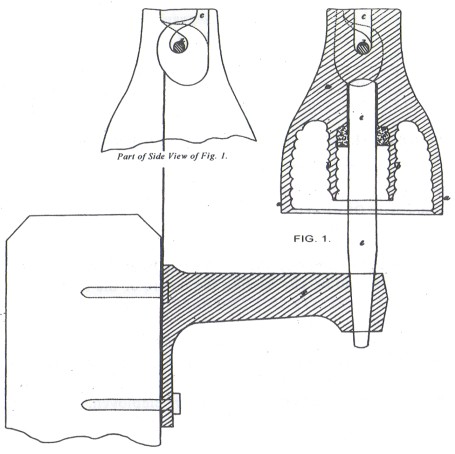
The Patent itself includes five scale drawings. The first three show the pin
of the insulator fitted into a socket formed at the end of an iron bracket --
first a vertical section, then views from the top and side. This entire unit is
then screwed to the side of a wooden post. The fourth and fifth drawings
describe a plan for using a slightly different type of iron bracket with a
socket, which is suitable for fixing on the top of a wooden post. I felt it was
unnecessary to include all five views of the insulator as it was mounted and
chose the one you see below because of its clarity. The Patent describes the
various parts of the insulator this way: "a is the exterior cup and b is
the interior cup of the insulator, and on the interior surface of the exterior cup and on both surfaces of the interior cup are formed a
series of circular grooves; c is the notch in the top of the insulator into
which the wire d drops, and the drawing clearly shows the way in which this hole
is undercut, so as to allow the wire to assume the position which it there
occupies; e is the iron bar cemented into the hole in the centre of the
bottom of the interior cup of the insulator."
It is interesting to note
that my U-2028 has neither the circular grooves on the skirt and inner skirt nor
a smooth pin hole, as shown in the drawing. The insulator was not on a pin when
I got it but the pin hole is threaded (6/inch) and there are remnants of cement
inside, which I'm sure was there to hold the pin more securely in place. This is
not uncommon because many times an insulator does not exactly match the Patent
drawing.
 |
 |
|
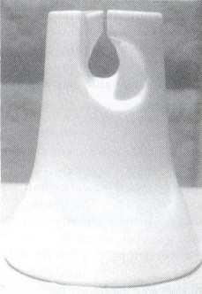
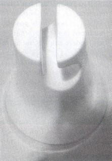
U-2028 photo on left shows the insulator viewed from the front, while the
right photo is looking down at the top of the insulator. |
Patent Drawing for
Joseph Latimer Clark's
Invention in Improvements
in
Electric Telegraphs.

___________________________________________
A.D. 1856. . . . . . . Noe 2831
________________________________
Electric Telegraphs
_______________
LETTERS PATENT to Joseph Latimer Clark, of Adelaide Road, Haverstock Hill,
Hampstead, for the Invention of "IMPROVEMENTS IN ELECTRIC
TELEGRAPHS." Partly a communication.
Sealed the 31st March 1857, and dated the 29th November 1856.
____________________________
PROVISIONAL SPECIFICATION left by the said Joseph Latimer Clark at the Office
of the Commissioners of Patents, with his Petition, on the 29th November 1856.
I, Joseph Latimer Clark, of Adelaide Road, Haverstock Hill, Hampstead, do
hereby declare the nature of the Invention for "IMPROVEMENTS IN ELECTRIC
TELEGRAPHS," to be as follows:-
This invention consists in an improved method
of insulating and supporting telegraph wires when such wires are suspended in
the air. For these purposes insulators of earthenware, glass or other similar
insulating material are employed. These insulators are of the form of an
inverted cup contained concentrically within the exterior insulating cup, and
springing from the interior thereof, so as to be protected by it. On the top of
the exterior inverted cup is formed a notch for receiving the wire. This notch
at the top is only wide enough to allow the wire to pass in, and is cut
obliquely to the direction of the wire, but lower down its sides are undercut in
such manner that when the wire is in its place the insulator can be turned partly round, which renders
it impossible for the wire to escape from the notch. The interior surface of
the exterior cup of the insulator has a series of circular grooves formed on its
inner surface, and the interior cup has similar grooves formed both on its
interior and exterior surfaces. In this way the distance to be traversed by the
electric current before it can escape is increased. In the centre of the bottom
of the interior cup of the insulator a hole is formed to receive the iron bar
(pin), by which it is carried, and which is cemented into the said hole. This
bar is coated with shellac, marine glue, or other suitable insulating material,
and its lower end is received by a socket at the end of a bracket of cast iron,
which is carried by the telegraph post. It will be seen that by mounting
insulators in this manner they may easily be taken down for cleaning, or
replaced by lifting the bar on which the insulator is mounted out of the socket
on the cast-iron arm, and by turning the insulator so as to separate it from the
wire.
| 
)
)
)
)